3D scanning and
reverse engineering.
We scan parts at our premises or on site and turn them into a clean STEP model that you can edit in any CAD program. Even without a drawing, and with a manufactured copy if you like.
- At our premises or on site
- Mesh (STL) or CAD (STEP)
- Accuracy up to 0.01 mm
- Quote within one working day
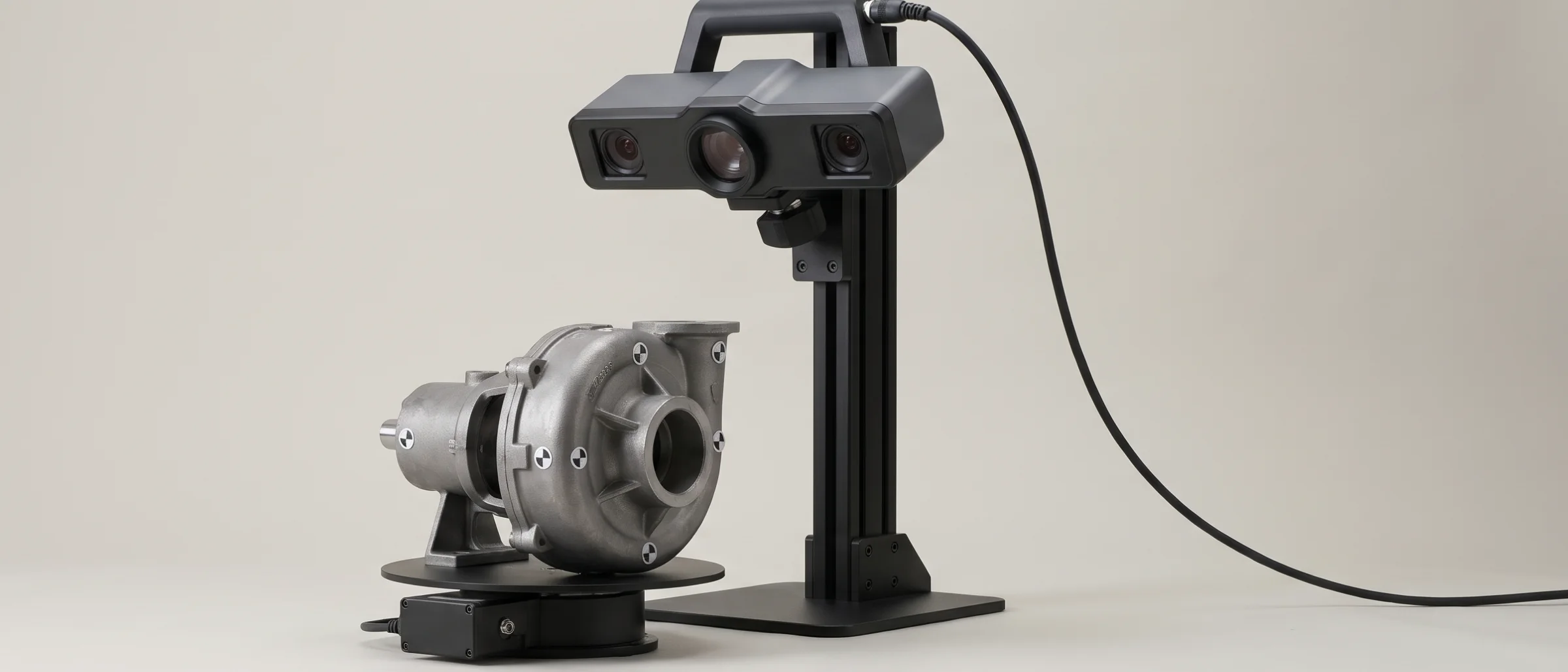






From physical part to STEP model.
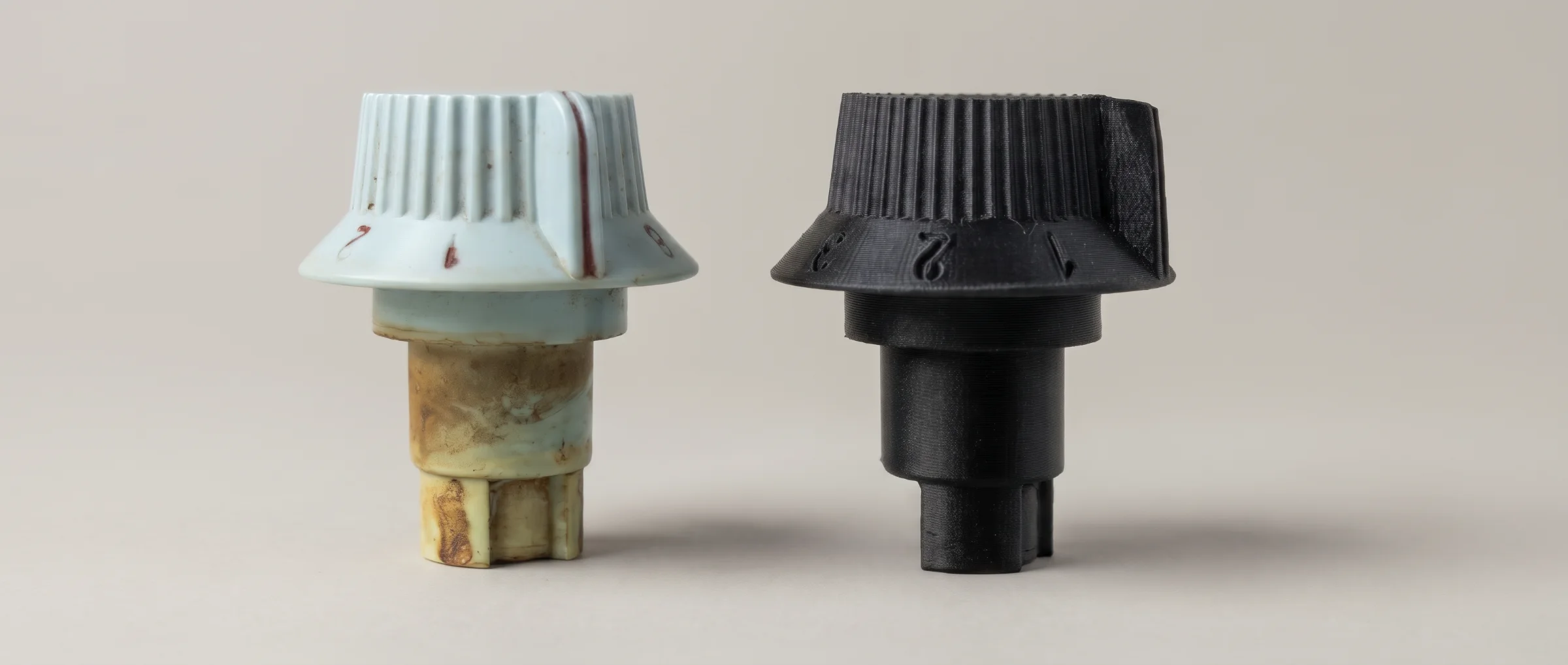
A spare part that is no longer available. A casting without a drawing. A hand-made prototype that is going into production. It starts with a physical part and ends with data you can work with.
A 3D scan captures the surface without contact, as a mesh of millions of measuring points. For a 3D-printed copy, an archive or an inspection, this mesh is often enough. If the part is to be modified, machined or fitted into an assembly, you need a CAD model.
That is where we are strongest: in reverse engineering we rebuild the part as a solid model in STEP, with real planes, holes and radii instead of triangles. You can keep editing the model yourself, or order the part from us straight away: 3D-printed, CNC-machined or in metal.
Mesh or STEP.
What you need in the end determines the effort. The two results compared.
Mesh model and CAD model compared
What it is
- Mesh model (STL, OBJ, PLY)
- The surface as a mesh of triangles, exactly as scanned
- CAD model (STEP)
- A solid model built from planes, cylinders, radii and freeform surfaces
Dimensions
- Mesh model (STL, OBJ, PLY)
- Measured values of the part, including wear and distortion
- CAD model (STEP)
- Nominal dimensions as agreed, for example 10.00 instead of 9.97 mm
Editing
- Mesh model (STL, OBJ, PLY)
- Limited, for example scaling or cutting
- CAD model (STEP)
- Fully editable in any CAD program: move a hole, thicken a wall, extend the part
Manufacturing
- Mesh model (STL, OBJ, PLY)
- 3D printing directly from the mesh
- CAD model (STEP)
- Any manufacturing process, including CNC milling and turning; basis for technical drawings
Typical use
- Mesh model (STL, OBJ, PLY)
- 3D-printed copy, archive, comparison with CAD, figures and art
- CAD model (STEP)
- Spare parts, further development, integration into assemblies, CNC production
Effort
- Mesh model (STL, OBJ, PLY)
- Low: scan and processing
- CAD model (STEP)
- Higher: modelled by hand, depending on the complexity of the part
Not sure what you need? Describe in your inquiry what should happen with the part. We will recommend the right result.
Reverse engineering in STEP.
A CAD model that looks as if it had been designed that way from the start.
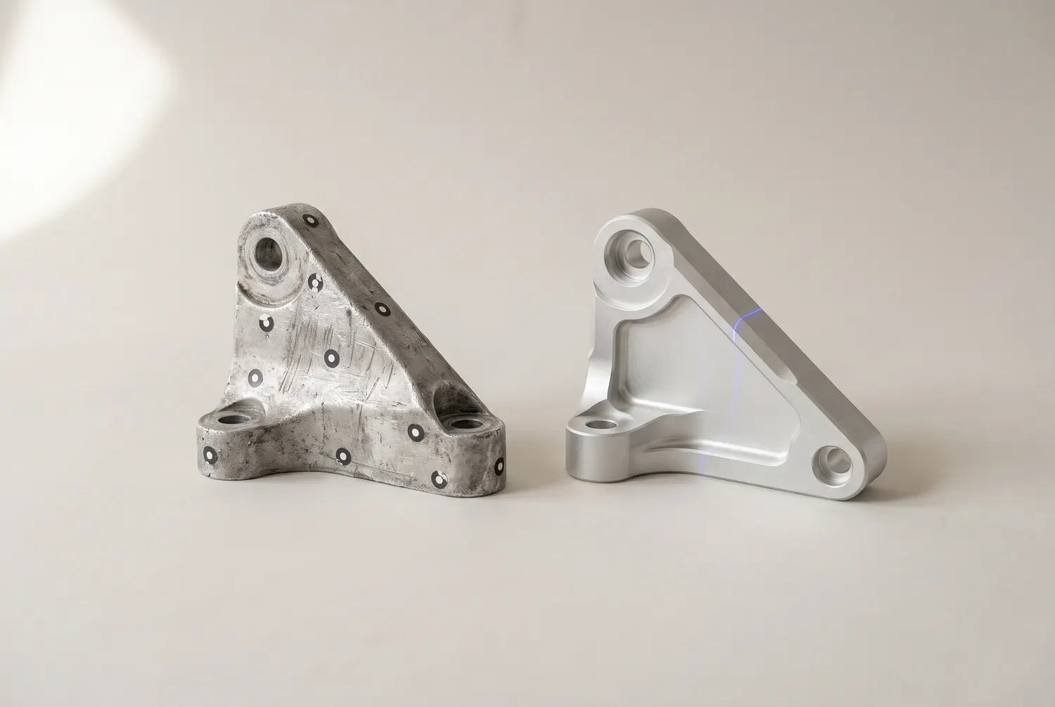
Real geometry instead of triangles
We model planes, cylinders, cones and holes as true geometry. The model opens in any CAD program as a clean solid, with no mesh remnants.Nominal dimensions and standard features
Where the scan measures 9.97 mm, it becomes 10.00 mm. Holes, threads and fits are set according to standards and your specifications.Compensating for wear and damage
We rebuild worn, broken or distorted areas to their original shape, using symmetry, mating parts or your information.Freeform surfaces
Handles, covers and organic shapes become smooth, continuous surfaces that can be manufactured.Aligned and checked
The model sits in a sensible coordinate system based on the functional surfaces. Before delivery, we compare it with the scan.Changes in the same step
A thicker wall, an extra hole, a different mating part: whatever you want to change, we build it in right away.
At our premises or on site.
We scan small and medium-sized parts at our premises, and large or permanently installed objects at yours.
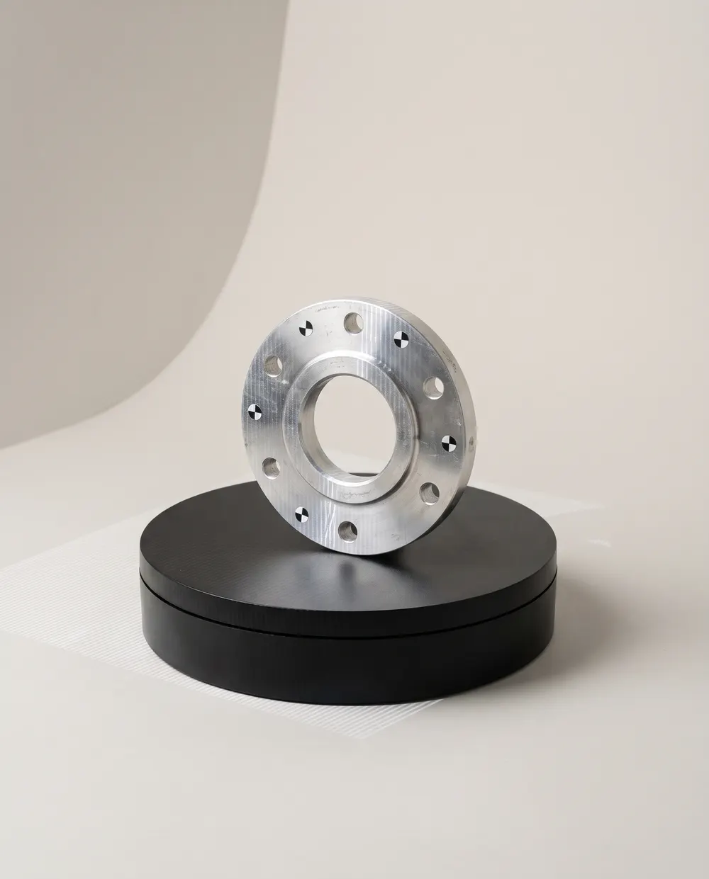
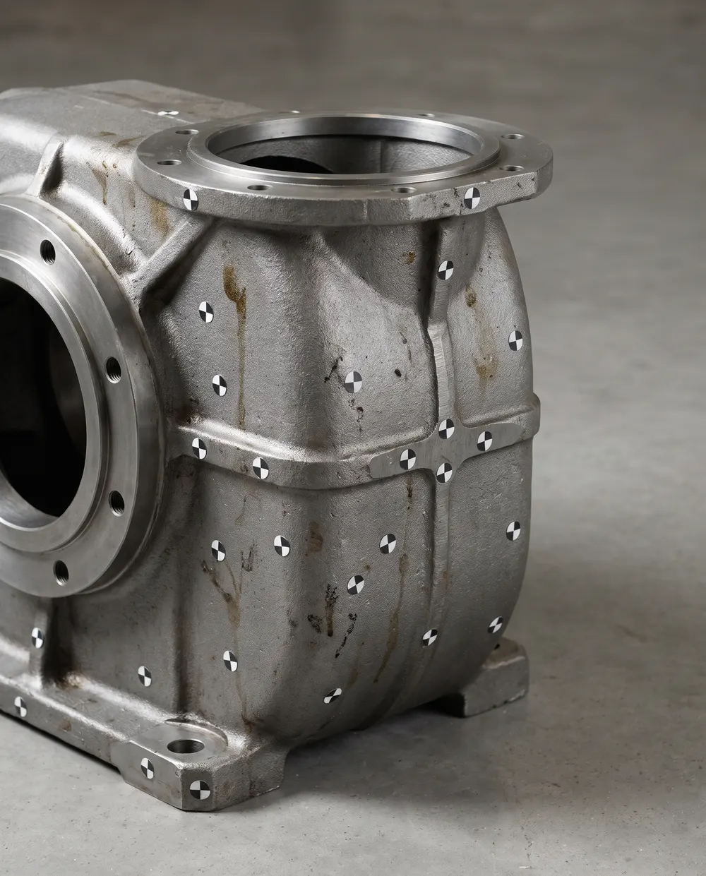
Scanning at our premises and on site
Suitable for
- At our premises
- Parts that can be shipped or dropped off
- On site
- Large, heavy or permanently installed objects: machines, plants, vehicles, moulds
Object size
- At our premises
- From small components up to about 1 m
- On site
- Up to several metres
Procedure
- At our premises
- Ship or drop off the part, you get it back with the data
- On site
- Book an appointment and we come to you with mobile scanners
Preparation
- At our premises
- Part clean, free of oil, dust and chips
- On site
- Access all around, machine switched off and secured, power outlet nearby
The original
- At our premises
- Stays with us only for the scan
- On site
- Stays with you, operations continue after the scan
The boundary is fluid. Based on photos, we work out with you which option makes more sense.
What customers have scanned.
Six typical tasks, often combined.
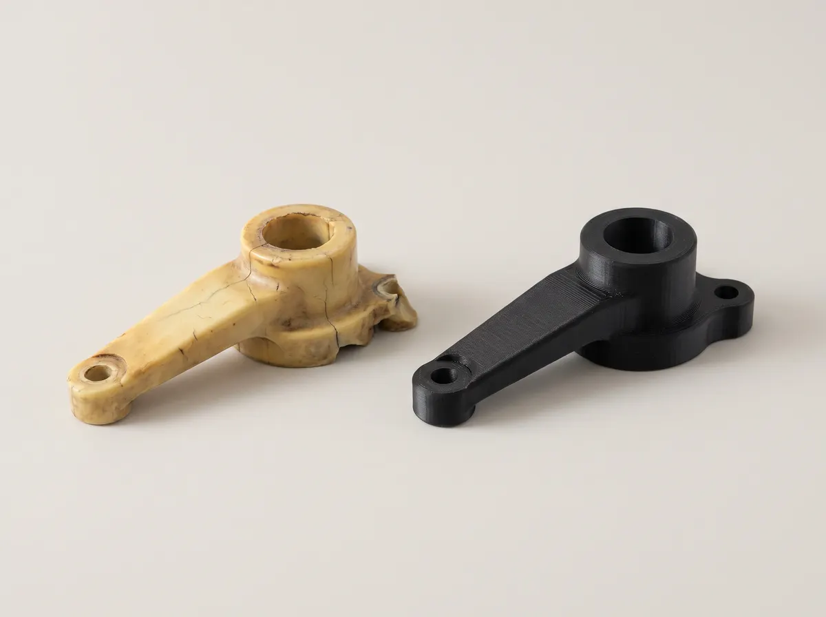
Spare parts without a drawing
A part has broken and the manufacturer no longer supplies it. We scan the original, add missing areas and produce the copy, even in a stronger material.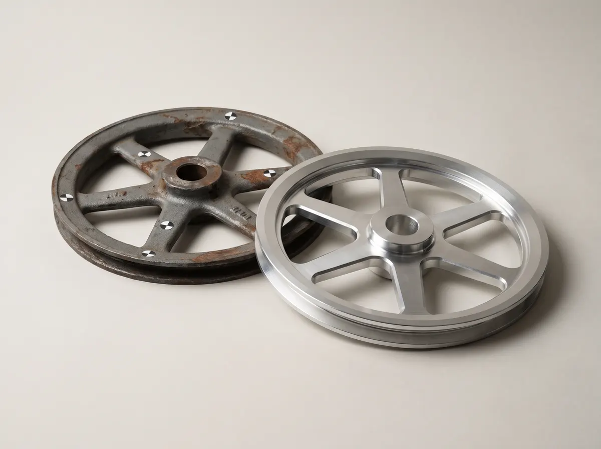
Remaking castings and old parts
Old cast and forged parts as a STEP model, produced as a CNC part or by metal 3D printing, without a new casting mould.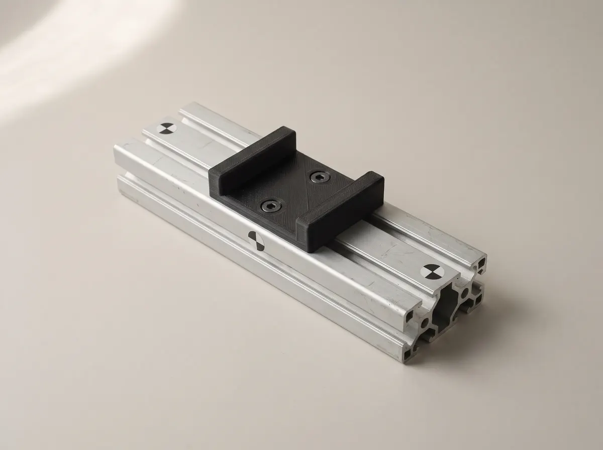
Fitting parts and add-ons
We scan the surroundings a part has to fit into, such as a centre console or a machine frame, and design brackets, covers or adapters on top.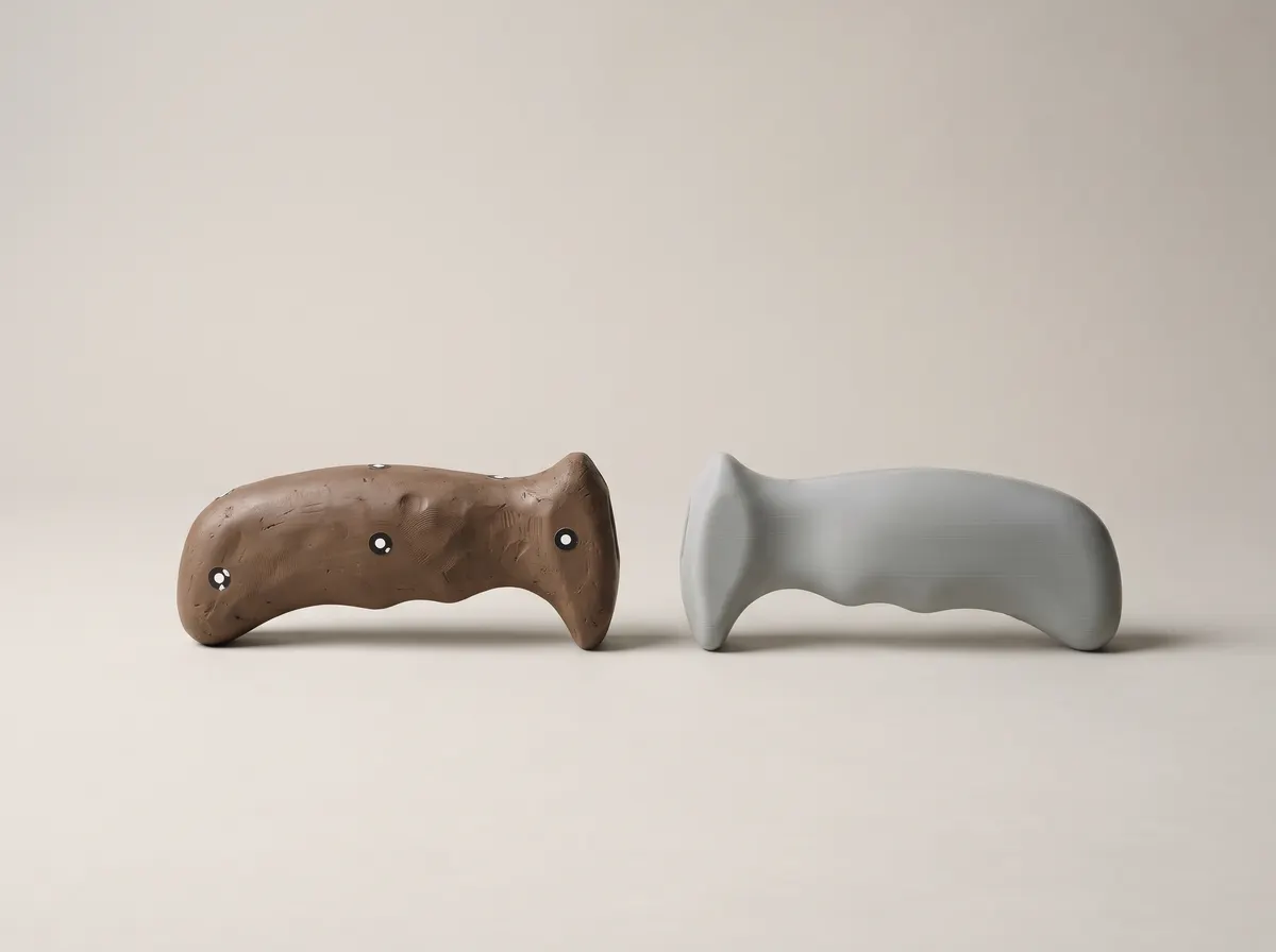
Design and hand-made models
Clay, foam or wooden models become CAD data for further development and the first prototype.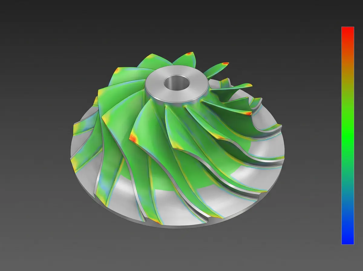
Comparison with CAD
Check a manufactured part against the CAD model: deviations become visible as a colour map, for example for first articles or distortion.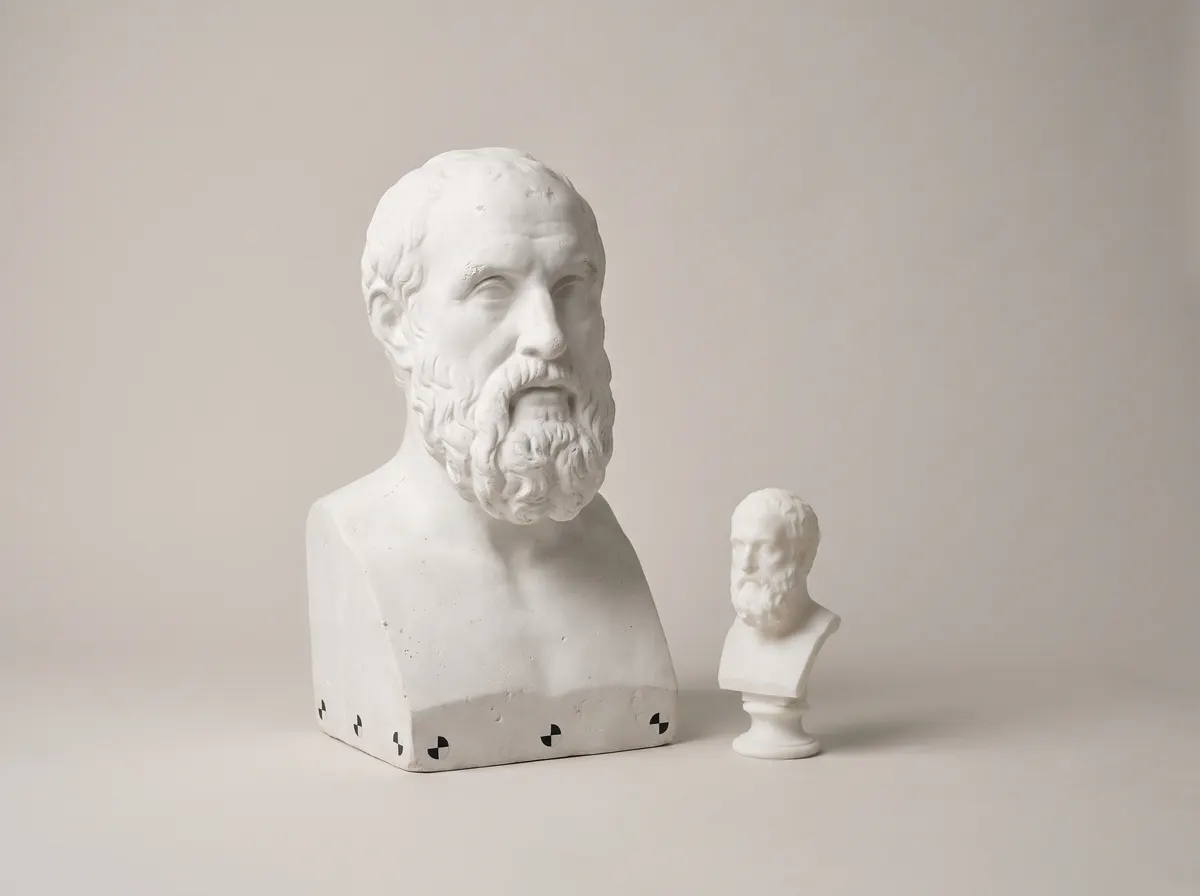
Figures, art and heritage
Digitally preserve, replicate or enlarge sculptures and objects, up to XXL figures.
Methods and surfaces.
We choose the scanner according to the size, detail and surface of the object.
Handheld laser scanner
Blue laser lines also capture dark and metallic surfaces. Portable, for parts from hand size up to vehicle and machine components.Structured light and industrial metrology scanners
Projected light patterns capture fine detail with high point density. For measuring tasks and high accuracy on large components, we use industrial systems.Infrared for large objects
Captures large areas quickly with somewhat less detail, for example body panels, plant components or figures.Shiny, black or transparent
Such surfaces reflect or absorb the light. A thin, temporary matting spray makes them scannable and can be removed afterwards. For delicate surfaces, we agree on this with you beforehand.Holes, threads and internal contours
A scanner only captures what it can see. We measure deep holes, threads and hidden surfaces by hand or take them from your information; parts that can be disassembled are scanned individually.Reference markers
Small adhesive dots help the scanner find its position. They peel off without leaving residue.
Data and formats.
You receive open standard formats that every CAD and printing program can read.
STEP
The solid CAD model from reverse engineering, for SolidWorks, Inventor, Fusion, Creo, Siemens NX, CATIA and all other common programs.IGES
Older exchange format for surfaces and solids, additionally on request.STL, OBJ and PLY
The mesh model from the scan, cleaned and closed, ready for 3D printing or visualisation.Deviation report
On request, the comparison between scan and CAD model as a colour map in PDF.
How an order works.
From the first photos to the finished data, with a manufactured part if you like.
Inquiry with photos
Photos from several sides, approximate dimensions and the purpose: copy, modification or inspection. You receive a quote with a date within one working day.Scan at our premises or on site
Ship the part or drop it off, or we come to you. The scan itself takes minutes to a few hours, depending on the object.Mesh or STEP
We process the scan and model the CAD part. Before delivery, we check it against the scan.Production on request
Copy or new part, 3D-printed, CNC-machined or in metal. You get the original back.
Frequently asked questions.
- It depends on the size, detail and surface of the part and on what you need in the end: a mesh model is quicker to produce than a STEP model with nominal dimensions. Send us photos and a short description and you will receive a binding quote within one working day.
- A 3D scan captures the surface as a mesh of measuring points. Reverse engineering turns it into a CAD model with real geometry, dimensions and radii that can be modified and manufactured. For a plain 3D-printed copy, the scan is often enough.
- An STL file is enough if you want to print, archive or inspect the part unchanged. You need a STEP model if you want to modify the part, have it milled or turned, fit it into an assembly or derive a drawing from it.
- Up to 0.01 mm, depending on the scanner and the size of the part. On large objects, the deviation grows with length, so we choose the scanner according to the required accuracy. In the STEP model, the nominal dimensions we agree with you then apply.
- Yes. We scan large, heavy or permanently installed objects such as machines, plants, moulds or vehicles at your premises. Smaller parts can be shipped to us or dropped off.
- From small components to objects several metres in size. Very fine details such as small lettering or thread turns are captured with a high-resolution scanner or added during modelling.
- Yes, with a thin, temporary matting spray. It makes the surface visible to the scanner and can be removed afterwards. For delicate surfaces, we agree on this with you beforehand.
- The scanner only captures visible surfaces. We measure deep holes, threads and hidden internal contours by hand or take them from your information. In the STEP model, they appear as standard geometry.
- Scan data is usually ready after 3–5 working days. A STEP model takes longer depending on complexity; we state the date in the quote.
- As STEP for all common CAD programs, additionally IGES on request, and as STL, OBJ or PLY for 3D printing and visualisation.
- No. Scanning works without contact, using light. Reference markers and matting spray can be removed afterwards, and you get the original back.
- Yes. With the STEP or STL model, we produce the copy by 3D printing, as a CNC part or in metal. For 3D printing, you see the price immediately when you upload the file in the configurator.
- Yes. In reverse engineering we can reinforce walls, add holes, eliminate weak points or adapt the part to a new mating part. Often a stronger material is the simplest improvement.
- Photos of the part from several sides, ideally with a ruler next to it, approximate dimensions, the purpose and the quantity required. For parts from an assembly, a photo of how it is installed helps.
- Yes. We use your parts and data only for your order. On request, we sign a non-disclosure agreement beforehand.
Have a part scanned.
Send us photos and a short description. You will receive a quote within one working day, for scanning at our premises or on site.
Sample images created with AI.