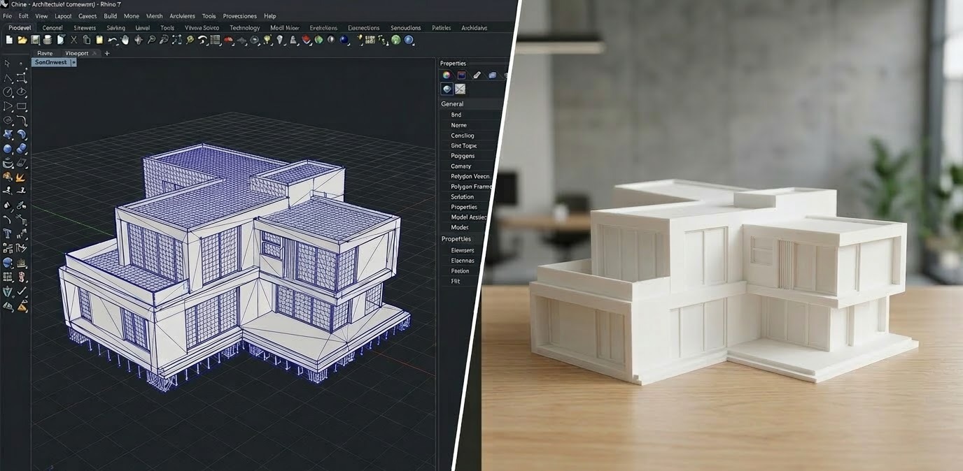
From architectural model to 3D print: How to make your data truly printable
The complete guide: Model preparation, design rules, and common mistakes in architectural 3D printing projects.

Elia Dubach
Head of Consulting
You’ve built an architectural model in ArchiCAD, Rhino, or Revit. It looks perfect on screen. Every window sits, every facade is correct, the proportions are exact. You export an STL file, send it to a 3D printing service provider and think: done.
And then the feedback comes: “Model not printable.”
This is not an isolated case. It’s the norm. Architecture software was developed to plan buildings, not to print them. What looks like a solid building on screen is often nothing more than a collection of surfaces that don’t fit together, walls that are too thin, and geometries that simply cannot exist in the physical world.
In this article, we show you how to prepare your architectural models so they are actually printable. Step by step, with concrete reference values and honest hints about where the typical pitfalls lie.
1. The basic problem: Why architectural models aren’t automatically printable
A 3D printer needs a so-called watertight model. This means: a closed, gap-free shell where it’s clearly defined what is inside and what is outside. Only then can the software slice the model into printable layers.
Architecture software works differently. It works with surfaces, solid bodies, and component logics optimized for floor plans, sections, and visualizations. A window in ArchiCAD is an intelligent component with parameters. For a 3D printer, it’s a hole in a wall that must be cleanly closed – or not, depending on the scale.
This leads to a fundamental difference: What is architecturally correct is often a problem for printing. And vice versa: What the printer needs is irrelevant in architectural planning. Closing this gap is the core of model preparation.
2. The right software: What Swiss architecture firms actually use
Before we talk about preparation, a look at the tools. In Switzerland, a few programs dominate the architecture landscape – and each brings its own strengths and weaknesses when it comes to 3D printing.
ArchiCAD is extremely widespread in Switzerland, especially in smaller and medium-sized firms. The software can export STL, but the results are often problematic. ArchiCAD models contain intelligent components that are converted into “dumb” geometry during export. This regularly produces non-manifold edges, overlapping surfaces, and open spots. Our advice: Export from ArchiCAD and plan for post-processing in a second program.
Rhino (Rhinoceros) is the unsung hero of model preparation. Many architecture firms already use Rhino for freeform geometries and complex facades. For print preparation, Rhino is by far the most versatile tool: It can process NURBS and meshes, has built-in mesh repair tools, and allows precise control over STL export. If you print regularly, there’s hardly a way around Rhino.
Revit is standard in larger firms and BIM projects. STL export works, but similar to ArchiCAD, the results are rarely directly printable. Revit models are optimized for building data modeling, not for manufacturing.
SketchUp is popular for quick design models and competitions. Its strength: SketchUp works natively with surfaces, which comes close to the mesh concept. Its weakness: SketchUp allows building geometries that are physically impossible.
For post-processing, two programs are particularly relevant: Meshmixer (free, by Autodesk) and Netfabb (also Autodesk, more powerful). Both can analyze and often automatically repair faulty STL files.
3. Making the model solid: The most important rule
No open surfaces, no holes, no intersecting geometries. Every element must be a closed solid body.
This sounds simple. In practice, it means a fundamental change in thinking.
Surfaces are not walls. In architectural visualization, a single surface is enough to represent a wall. In 3D printing, a surface without thickness does not exist.
Components must be united or separated. When two solid bodies interpenetrate, it must be clear: Are these separate parts or a single body?
Normals must point outward. Every face in a mesh has a front and back side. If individual faces are “flipped,” the printer no longer knows what’s inside and what’s outside.
Check your model before export. In Rhino there’s the “Check” and “SelNonManifold” command. In SketchUp the “Solid Inspector.” In Meshmixer or Netfabb the automatic analysis.
4. Minimum wall thicknesses: What the printer can actually do
This is the point where most architectural models fail.
The minimum wall thickness depends on the printing process. Here are the reference values:
| Process | Min. wall thickness | Recommendation |
|---|---|---|
| FDM | 1.2 mm | 1.5 mm for delicate structures |
| SLA | 0.6 mm | 0.8 mm for freestanding walls |
| SLS | 0.7 mm | 1.0 mm recommended |
For architectural models at scale 1:500 to 1:200, this means concretely: exterior walls that are 20 cm thick in reality are only 0.4 mm at scale 1:500. That’s too thin for most printing processes.
An honest rule of thumb: Plan with at least 1.0 mm at 1:500 scale, 0.8 mm at 1:200 scale.
5. Design guidelines: What to consider when modeling
Details and minimum sizes. Every printer has a minimum detail resolution. For FDM it’s about 0.8 mm, for SLA about 0.3 mm.
Overhangs and support structures. Geometries that begin in mid-air need support structures in FDM and SLA printing. In SLS, no supports are needed.
Clearances and gaps. Plan a gap of at least 0.3 mm if separate components are to be joined after printing.
Base and standing surface. Plan the base directly into the model, at least 2 to 3 mm thick.
Labels and engravings. Text works best as raised lettering with a minimum height of 0.5 mm.
6. STL export: Settings that make the difference
STL describes your model’s surface as a mesh of triangles.
Exported too coarsely – and your model looks like a Minecraft building. Too fine – and you create files with hundreds of megabytes.
The right setting is in between.
Important: Check units. STL files contain no unit information. Scale the model to millimeters before export.
Multiple parts or one piece? As a rule: If the model fits on the build platform, one piece. If not, split sensibly.
7. Common mistakes: What we see again and again
After hundreds of architectural models, we know the recurring problems:
Walls without thickness. The most common mistake of all. Surfaces instead of solid bodies.
Non-manifold edges. Edges where three or more faces meet.
Double faces. Two identical faces on top of each other.
Forgot the scale. The model is in meters instead of millimeters.
Too many details at the wrong scale. Interior furnishings, door handles, outlets – invisible at 1:500.
Terrain as a surface only. Terrain models need a base plate and closed side walls.
Trees and vegetation. Use simplified, stylized tree shapes modeled as closed bodies.
8. A proven workflow: Step by step to a print-ready model
A workflow that has proven itself in practice:
Define scale and scope
Which scale? Which building section? Which details are relevant?
Simplify model
Remove everything that doesn’t contribute to the physical model.
Check and adjust wall thicknesses
Make sure minimum wall thicknesses are met.
Repair geometry
Check, SelNonManifold, Solid Inspector, or automatic repair.
Export STL
With the right settings. Check units.
Final check
Visually inspect the exported STL.
Send to service provider
With details on process, material, scale, and post-processing wishes.
What you should take away
Preparing an architectural model for 3D printing is not rocket science, but it’s also not a one-click operation.
The good news: Most problems are predictable and solvable with reasonable effort.
And if all of this is too much effort: Send us your model as is. We’ll look at it, tell you what needs to be adjusted, and can handle the preparation for you if desired. That’s what we’re here for.
Submit model & get consultation