From physical object to digital model – and back
The complete workflow: 3D scanning, reverse engineering and 3D printing explained

Elia Dubach
Head of Consulting
You’re holding a component in your hand. No CAD file, no technical drawing, no documentation. Maybe it’s a spare part that hasn’t been produced for years. Maybe a prototype that needs further development. Or a component you want to reproduce – identically, slightly modified, or in a completely different material.
Now what? Now begins the journey from the physical object into the digital world. And if you wish, back again.
In this article, we show you the complete process – step by step. Not as a sales brochure, but as an honest explanation: What happens when, why, and above all – what do you actually need?
1. The physical object: Where it all begins
Before a scanner is even used, a fundamental question arises: What do you want to do with the digital data in the end?
Sounds trivial. But it’s not. Because the answer determines the entire workflow – how precisely the scan needs to be, what post-processing is required, and whether you need a mesh or a complete CAD model at the end.
A few typical scenarios:
“I need an exact copy.” You have a working part and want to reproduce it – same geometry, same dimensions. A clean scan with subsequent data preparation is often sufficient. No reverse engineering needed.
“I want to modify the part.” You have an existing component, but it needs to be adapted: different wall thickness, additional bore, new feature. Then you need an editable CAD model – and thus reverse engineering.
“I need digital documentation.” Archiving, quality control, nominal-actual comparison. This is about precise measurement data, not necessarily printability.
“I only have a vague idea and a similar part.” Then the scan is your starting point for a new design – a reference, not a final product.
Why does this matter? Because it massively influences the effort involved. A scan with simple mesh preparation is done in a few hours. Complete reverse engineering can cost several times that depending on complexity. Those who know from the start where the journey is headed save time and money.
2. The 3D scan: The bridge between reality and screen
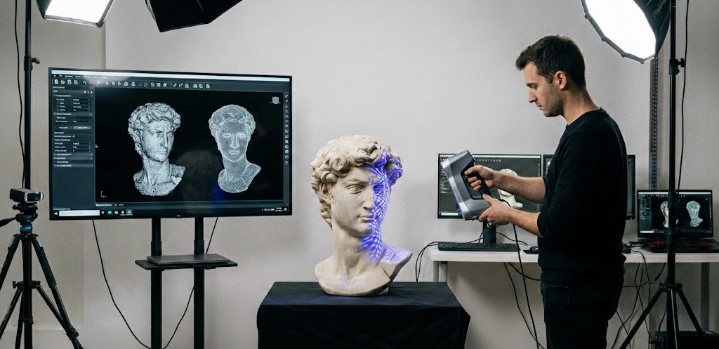
Now it gets concrete. The physical object is transferred into the digital world – through a 3D scan. The scanner samples the surface of the object and captures millions of individual measurement points in space. The result is a so-called point cloud: a three-dimensional map of the surface, point by point.
Different technologies are used depending on the requirements:
Structured Light works with projected light patterns and is excellent for small to medium-sized components with high detail accuracy.
Laser scanners are the all-rounders – from small components to entire vehicles or rooms.
Photogrammetry uses photos from different angles and is particularly suitable for large objects or when a scanner cannot be used on site.
What all methods have in common: They capture the surface – not the interior. A 3D scan shows you what an object looks like, not what it’s made of or how it was designed. This is an important distinction that becomes relevant in the next step.
What can go wrong
Not every object can be easily scanned. Shiny surfaces reflect the scanner’s light and create interference signals. Transparent materials – glass, clear plastics – are practically invisible to most scanners. Very dark surfaces absorb too much light.
The solution in most cases is a temporary matting spray that applies a thin, scannable layer to the surface. After the scan, it is simply removed. This works reliably but should be discussed beforehand for sensitive surfaces.
The geometry itself also plays a role. Deep bores, narrow gaps, or completely hidden inner surfaces cannot be captured by any scanner if there’s no line of sight. Here, post-processing must fill in the gaps – or multiple scans from different positions are combined.
3. From scan to mesh: Cleaning up data
What the scanner delivers is raw material first. The point cloud must be converted into a so-called mesh – a closed triangle network that describes the surface of the object. Think of it as an extremely fine wire grid that fits exactly around the shape of the object.
This step sounds automatic, but it’s only partially so. The software does most of the work, but almost every scan needs manual post-processing:
Remove noise. No scan is perfect. Individual points are not where they belong. These outliers must be cleaned up before they distort the surface.
Close holes. Wherever the scanner couldn’t capture data – obscured areas, difficult angles – gaps appear in the mesh. These are intelligently closed, either through interpolation or manually.
Smooth and optimize. Depending on the intended use, the mesh is smoothed, the triangle count reduced (for smaller file sizes), or the resolution increased in certain areas.
The result is an STL, OBJ, or PLY file. And here’s the crucial point: A mesh is a shell. It describes the surface precisely, but it doesn’t “understand” the object. It knows no dimensions, no radii, no design logic. It’s like a 3D photo – true to detail, but not editable.
For many applications, this is perfectly sufficient. If you want to print a 1:1 copy, create a display model, or digitally archive the object, the mesh is your end product. You can send it directly to 3D printing. But if you want more – you need the next step.
4. Reverse engineering: Truly understanding the component
Reverse engineering is the process by which a “dumb” mesh becomes an intelligent, parametric CAD model. A file in which not just triangles describe the surface, but in which every bore has a defined diameter, every fillet an exact radius, and every surface a geometric relationship to the others.
The difference is fundamental. A mesh says: “Here is roughly a round shape with roughly this diameter.” A CAD model says: “Here is a bore with 8.00 mm diameter, 12.50 mm deep, centered on this surface.” One you can look at. The other you can modify.
How does it work in practice?
The mesh is placed in the CAD software as a reference – like a semi-transparent template. The engineer then overlays geometric primitives: planes, cylinders, cones, freeform surfaces. Step by step, the component is reconstructed – not estimated, but with exact dimensions derived from the scan.
For organic forms – sculptures, ergonomic handles, body parts – freeform surfaces (NURBS) are used. These are more complex but allow the reproduction of geometries that cannot be described with simple primitives.
When is reverse engineering necessary?
Not always. And that’s important to know, because it’s the most complex step in the entire process. Reverse engineering is worthwhile when:
Sie das Bauteil modify or optimize wollen – neue Features, andere Masse, bessere Geometrie.
Es ist nötig, wenn das Teil für conventional manufacturing vorbereitet werden soll, also CNC-Fräsen oder Spritzguss, die saubere CAD-Daten mit Toleranzen erfordern.
Es macht Sinn, wenn Sie ein reproduce a worn part und dabei den Verschleiss korrigieren wollen – also nicht die abgenutzte, sondern die ursprüngliche Geometrie rekonstruieren.
Und es ist unverzichtbar, wenn das Teil in eine integrated into an assembly werden soll, bei der parametrische Abhängigkeiten eine Rolle spielen.
When can you skip it?
If you need a pure copy – same shape, same material, same size – the prepared mesh is sufficient. Straight to print, done. You also don’t need reverse engineering for display models, archiving, or visualization.
The decision between mesh and CAD is not a quality question – it’s a question of purpose. Both have their justification.
5. From digital model back to physical object
Now the circle closes. The digital model – whether mesh or CAD – is turned back into a physical object. Through 3D printing, CNC machining, or another manufacturing process.
In 3D printing, the model is divided into layers and built up layer by layer. Which process is used depends on the requirements:
FDM for functional plastic parts, prototypes, and small series. Robust, fast, cost-efficient.
SLA for parts requiring fine details or smooth surfaces. Ideal for visual parts and models with high detail accuracy.
SLS for mechanically durable parts without support structures. Nylon, glass-fiber reinforced, in series quality.
SLM for metal. Titanium, stainless steel, aluminum – directly from the powder bed.
And here the great advantage of the digital twin becomes apparent: The model now exists. You can reprint it at any time – in the same or different material, in a different size, with modifications. You can retrieve it in five years when a spare part is needed. Or in ten years. The physical object wears out. The digital model doesn’t.
The complete cycle at a glance
This makes the whole thing tangible: You start with a physical object and no digital basis whatsoever.
In the first step, the object is transferred into a point cloud via 3D scan – the raw digital capture of the surface. This point cloud is then converted into a mesh and processed: remove noise, close holes, optimize the surface.
At this point comes the central decision: Is the mesh sufficient for your purpose, or do you need a full CAD model? For a direct copy or archiving, the mesh goes straight to print. For modifications, further development, or conventional manufacturing, reverse engineering follows – the mesh becomes the reference for CAD reconstruction.
In both cases, the end result is a new physical object: identical, optimized, or completely reinterpreted. Plus a digital twin that can be retrieved at any time. The entire process – from object to scan to model to print – is not a one-way street. It’s a cycle. And that’s exactly what makes it so powerful.
What does this mean in practice?
A concrete example: A mechanical engineering company has an aluminum bracket in use that regularly wears out. The drawings? No longer exist – the part was designed 20 years ago, the documentation has been lost.
The path via 3D scan and reverse engineering delivers a complete CAD model within a few days. The current state is not simply mapped – the wear is corrected: bores get their nominal dimensions back, bearing surfaces are straightened.
With the new CAD model, the customer now has several options: Have it manufactured immediately via 3D printing in nylon or metal. Or use the model for CNC manufacturing if larger quantities are needed. Or both – a quick 3D print as an immediate solution and conventional manufacturing in parallel.
In any case, a digital twin now exists that didn’t exist before. The next spare part is an order away, not a three-month procurement project.
What you should take away
The path from physical object to digital model is not rocket science – but it has different stages that are not always all necessary. A good scan with clean mesh preparation is sufficient for many applications. Reverse engineering is worthwhile when changes are planned or clean CAD data is needed. And the way back from digital to physical is faster and more flexible than ever with modern manufacturing processes.
The decisive advantage of the entire process is not the individual step – it’s the fact that you end up with a digital twin. A model that doesn’t age, doesn’t wear out, and can become a physical object again at any time.
Häufige Fragen zu 3D-Scan & Reverse Engineering
Was kostet ein 3D-Scan bei Swiss3D?
Der Preis hängt von Objektgrösse, Komplexität und gewünschtem Ausgabeformat ab. Einfache Industrieteile starten ab wenigen Hundert Franken; aufwendige Reverse-Engineering-Projekte mit vollständiger CAD-Rekonstruktion werden nach Aufwand (CHF 120/h) abgerechnet. Kontaktieren Sie uns für ein unverbindliches Angebot.
Welche Objektgrössen können gescannt werden?
Swiss3D scannt Bauteile von wenigen Millimetern bis zu mehreren Metern Grösse. Für sehr kleine Präzisionsteile setzen wir hochauflösende Strukturlichtscanner ein, für grosse Fahrzeug- oder Maschinenkomponenten mobile Laserscanner.
Kann ich ein gescanntes Bauteil direkt drucken lassen?
Ja – nach der Scan-Aufbereitung liegen druckfertige STL-Daten vor. Swiss3D fertigt Ihr Bauteil auf Wunsch direkt im Anschluss in FDM, SLA, SLS oder SLM. So erhalten Sie vom Scan bis zum Druck alles aus einer Hand.
Was ist der Unterschied zwischen Mesh-Aufbereitung und CAD-Rekonstruktion?
Die Mesh-Aufbereitung bereinigt und optimiert die Scandaten (STL) für den 3D-Druck oder die Visualisierung – schnell und kosteneffizient. Die CAD-Rekonstruktion erstellt daraus ein parametrisches STEP/IGES-Modell, das verändert, bepaszt oder in bestehende Baugruppen integriert werden kann. Welche Variante sinnvoll ist, hängt vom Verwendungszweck ab.
Wie genau ist 3D-Scanning für Reverse Engineering?
Unsere Strukturlicht- und Laserscanner erreichen Messgenauigkeiten von bis zu 0,01 mm. Die erreichbare Genauigkeit hängt von Objektgrösse, Oberflächenbeschaffenheit (reflektierend, transparent) und der gewählten Scan-Methode ab. Für technische Präzisionsbauteile empfehlen wir Strukturlicht; für grosse Objekte optimierte mobile Laserscanner.
Conclusion
If you have a component that should take this path – whether as a simple scan or complete reverse engineering – get in touch with us. We’ll take a look and honestly tell you which steps are truly necessary in your case.
Request 3D scan now