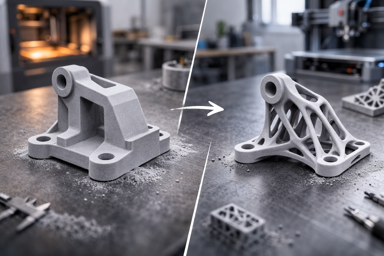
Optimizing 3D models for 3D printing
A guide for all printing processes

Elia Dubach
Head of Consulting
You have a 3D model. Perhaps self-designed, perhaps delivered by a designer, perhaps created via reverse engineering from a scan. Now it needs to be printed. And here begins the part that most people underestimate: The model doesn't just need to exist. It needs to work for the chosen printing process.
A CAD model that looks perfect on screen is far from being a good print model. The geometry must match the technology and the wall thicknesses must be correct. And if you want to produce in series, you need to think differently than for a one-off piece.
This article is not a superficial overview. It's an honest guide that shows you what really matters in design. So that you don't have to revise your model three times before it's printable.
But before you think it's all terribly complicated: Don't worry. Most models we receive are already pretty close. Often it's small things that make the difference. A wall thickness here, a bore there. And even if your model isn't print-ready yet: We won't leave you alone with it. Every model is checked by our engineers before printing. If we notice something that should be adjusted, we'll proactively reach out to you. You don't need to be a 3D printing expert to get good results with us. That's what we're here for.
1. Before you start: Rules that always apply
Whether FDM, SLA, SLS, MJF, or SLM: There are principles that apply across all processes. Those who internalize these save themselves revisions on every single project.
Watertight geometry is mandatory. This sounds obvious, but it's the most common error of all. Your model must be a closed volume. No open edges, no intersecting surfaces, no inverted normals. Every slicer software will have problems with a non-manifold mesh. Some repair it automatically, but you should never rely on that. Check your model before export with a mesh analysis. In Fusion 360, SolidWorks, or even free in Meshmixer, this can be done in seconds.
Maintain minimum wall thicknesses. Every printing process has physical limits. A wall that is 0.3 mm thin in CAD simply won't be printed in FDM. In SLS maybe, but it will be so fragile that it breaks during de-powdering. The specific minimum wall thicknesses and design guidelines can be found on the corresponding material page in our Material Finder. But the basic rule is: Never design at the absolute minimum. Give yourself margin.
Understand tolerances. 3D printing is not CNC milling. Depending on the process and material, achievable tolerances range between ±0.1 mm and ±0.5 mm. Anyone who needs fits must consider this during design. A bore that is exactly 10.00 mm in CAD will not be exactly 10.00 mm in print. Plan clearance, process-specifically. Here too, a look at our Material Finder helps: There you'll find the achievable tolerances per process and material.
Choose the right file format. A high-resolution STL file is perfectly sufficient in most cases. When exporting, ensure sufficiently fine resolution (chord deviation below 0.01 mm for precise parts) so that curves don't become visible facets. But don't overdo it: A 500 MB file for a 5 cm component is neither necessary nor helpful. For large models or parts with many curves and freeform surfaces, we recommend STEP as file format. STEP transfers the exact mathematical geometry instead of a triangle approximation, which can make a noticeable quality difference in printing for large components or complex curves.
2. FDM: Think layer by layer
Fused Deposition Modeling is the most widespread process. A plastic filament is melted and applied layer by layer. It sounds simple, but the physics behind it significantly determines the design.
Overhangs and support structures. FDM prints from bottom to top. Each layer needs something to rest on. For overhangs over 45°, support material is needed. This means: more material consumption, more print time, and marks on the surface. The best optimization is to avoid or at least reduce overhangs. Chamfers instead of right-angle transitions. Teardrop-shaped instead of circular cavities. Keep bridges short (under 10 mm usually works without support).
FDM parts are anisotropic. In the print plane (XY) they are significantly stronger than between layers (Z). A hook printed in Z-direction breaks at the layer boundary. The same hook, rotated 90°, holds many times more. Our engineers choose the optimal print orientation for your part. But if you know where the greatest loads occur, this information helps us enormously. Tell us the load directions so we can optimally orient the part.
Holes and tolerances. Bores in FDM generally turn out smaller than designed. This is because the printer assembles curves from straight segments and the molten plastic contracts slightly when cooling. Rule of thumb: Design bores 0.2 to 0.4 mm larger than the nominal dimension. For dowel pins or screw connections, we recommend a sample part first.
Avoid elephant foot. The first layers of an FDM print are often slightly wider than intended because the print bed slightly compresses the plastic. If dimensional accuracy at the bottom is important, plan a small chamfer (0.5 mm) at the contact edge. This elegantly solves the problem at the design level.
3. SLA: Precision in geometry
Stereolithography works with UV light that cures liquid resin layer by layer. The results are significantly finer than with FDM, but the process has its own requirements for geometry.
Hollow bodies with drainage holes. If you design large, solid parts, you waste material unnecessarily, and the part can warp due to internal stresses. Better: Design hollow bodies and provide drainage holes (at least 3 mm diameter, preferably 5 mm) so that uncured resin can drain. Without drainage holes, liquid resin remains trapped inside, which can lead to cracks in the long term.
Support structures are unavoidable, but plannable. With most SLA printers, the part hangs upside down from the build platform. Support structures are almost always necessary and leave marks on the surface. If you know which sides of your part are visible surfaces, tell us. Our engineers then orient the part so that supports land on non-critical surfaces. What you can do in design: Avoid large, flat surfaces that would have to be parallel to the build platform. Such geometries create large suction forces at each layer and are generally problematic in SLA printing.
Use fine details strategically. SLA can produce impressively fine details. Positive features (elevations, ribs, text) from 0.2 mm. Negative features (engravings, channels) from 0.3 mm. For text on surfaces: Raised text works better than recessed, and the minimum letter height should be 3 mm for good readability. The exact minimum wall thicknesses and detail sizes can be found in our Material Finder for the respective SLA resin.
4. SLS and MJF: The series processes
Selective Laser Sintering (SLS) and Multi Jet Fusion (MJF) are the processes where 3D printing stops being pure prototyping and transitions into series production. Both work with powder bed and need no support structures because the unsintered powder supports the part during printing. This fundamentally changes design freedom.
Use design freedom. No supports means: You can realize geometries that are impossible with any other process. Interlocking chains, integrated hinges, internal channels, nested assemblies. Use it. The greatest strength of SLS and MJF is not printing existing designs 1:1, but enabling designs that would be impossible for conventional manufacturing.
Consider de-powdering. After printing, your part is stuck in a block of loose powder. This powder must be completely removed. This becomes a problem with narrow channels (under 4 mm diameter becomes difficult), deep pockets, or closed cavities. Always design openings through which powder can escape. Channels should have at least 4 mm inner diameter if they are longer than 20 mm. For long channels, inspection openings along the path help.
Warpage with large surfaces. Both SLS and MJF work with high temperatures. Large, flat surfaces tend to warp. From a surface of about 150 x 150 mm, it becomes critical. Counter-strategies: Add ribs on the back, slightly curve the plate (design counter-warp), or increase wall thickness. Better yet: Adapt the design so that no large flat surfaces are necessary.
Minimum dimensions and fine structures. The specific minimum wall thicknesses for SLS and MJF materials can be found in our Material Finder. Generally: Fine pins and posts should not be designed too slender, especially if they are cantilevered. Features that are mechanically stressed during de-powdering need a safety margin.
5. SLM: Metal has its own rules
Selective Laser Melting prints metal parts directly from powder. Titanium, stainless steel, aluminum, tool steel. The possibilities are enormous, but the design rules are the strictest of all processes.
Support structures are mandatory. Unlike SLS, metal printing almost always needs supports. Not only to support overhangs, but primarily to connect the part to the build platform and dissipate heat. Metal gets extremely hot during printing, and without sufficient thermal connection, the part warps or cracks. Design your part so that supports can be cleanly removed: plan access for tools, don't force supports in inaccessible areas.
Account for thermal stresses in geometry. Metal printing generates enormous thermal stresses. The longer and thinner a feature, the higher the risk of warping. Massive cross-section changes create stress concentrations. Design transitions smoothly, avoid abrupt thickness changes, and think in uniform wall thicknesses.
Powder removal from cavities. Just like with SLS, unsintered powder must be removed. With metal, this is even more critical because the powder is significantly heavier and harder to dislodge. Internal channels need sufficient diameter, and every cavity needs at least two openings for powder to trickle out. Trapped metal powder is not only material waste but a real safety risk in medical or aerospace applications.
Overhangs and angles. Metal printing allows overhangs up to about 45° without support. Anything below needs support structures. Horizontal surfaces on the underside (downskin) have a significantly rougher surface than vertical surfaces or upskin areas. If surface quality is important, tell us which surfaces are critical. Our engineers consider this when orienting the part in the build space.
Machining allowance for functional surfaces. Surfaces that will be CNC post-machined (fits, sealing surfaces, threaded holes) need a machining allowance of 0.5 to 1.0 mm per side. And remember: The part must be clampable. Plan clamping surfaces into the design.
6. Design for series: Think differently
Printing individual parts and prototypes is one thing. But if you want to produce a hundred, five hundred, or a thousand identical parts, different rules apply. Series production in 3D printing works, but only if the design is built for it from the start.
Optimize nesting. In powder-based processes (SLS, MJF), many parts are placed simultaneously in the build space. The more parts fit into a build job, the cheaper each piece becomes. This means: Compact geometries are cheaper than sprawling ones. A part measuring 50 x 50 x 50 mm packs much better than one at 200 x 30 x 10 mm, even if the volume is similar. If you have the choice, prefer compact shapes.
Ensure repeatability. What is still acceptable for a prototype becomes a problem at 500 parts if dimensional accuracy doesn't hold. Identify the critical dimensions of your part and discuss achievable tolerances with us before going into series.
Marking and traceability. In series production, every part needs identification. Design part numbers, batch numbers, or QR codes directly into the model. Raised text on a flat surface is the most reliable method. The minimum font size depends on the process, but plan generously: Text that turns out too small cannot be corrected afterward.
Design for assembly. If the printed part is integrated into an assembly, think about assembly. Self-centering features (chamfers on fits, lead-in angles, snap-fits) massively speed up assembly. In 3D printing, you can realize features that would be uneconomical in conventional manufacturing: integrated spring elements, living hinges, pre-assembled assemblies. Use it.
Function integration. The biggest lever in series optimization is not the individual part, but the reduction of part count. Can you combine three individual parts into one? Can you integrate threads, sealing lips, or guide grooves directly into the part instead of as separate components? Every part that doesn't need assembly saves costs in manufacturing, in the warehouse, and in logistics.
7. Think material and geometry together
Model optimization doesn't end with pure form. The material influences how you should design.
Shrinkage and warpage. Every material shrinks when cooling, and at different rates. In areas with very different wall thicknesses or with long, thin parts, warpage can be locally stronger than expected. Avoid abrupt wall thickness transitions. Design transitions smoothly. Symmetric cross-sections warp less than asymmetric ones.
Moisture absorption. Nylon (PA12, PA11) absorbs moisture and changes its dimensions and mechanical properties. If dimensional stability over time is important, consider this in material selection. Here too, our Material Finder helps: There you'll find the relevant material properties and can compare specifically.
Heat resistance. If your part is exposed to heat, not only choose the material accordingly but also design with the thermal expansion coefficient of the material. A part that fits perfectly at room temperature may jam in its receptacle at 80°C. Plan for thermal expansion in fits and guides.
8. Common mistakes and how to avoid them
At the end of this guide, a look at the mistakes we see most often. Not to point fingers, but because almost everyone makes them at least once.
Designed too thin. The classic. "It looks good in CAD" is not proof of printability. Check every wall thickness against the minimum values of the chosen process in our Material Finder. And then add a safety margin.
Support structures not considered. Anyone who designs their model without thinking about printability gets a part that is either full of supports or not printable at all. Avoid unnecessary overhangs where function allows. Our engineers take care of the rest.
Designed for the machine, not for the process. Many designers transfer CNC thinking to 3D printing. Fillets on every edge that are necessary in milling are often unnecessary in 3D printing and only create additional complexity. Conversely, the specific strengths of 3D printing are not used: undercuts, lattice structures, function integration. Think in terms of the process's possibilities, not the limitations of conventional manufacturing.
Forgot scaling. This sounds trivial but happens regularly: The model is designed in inches, the slicer interprets millimeters. Or vice versa. Check the units and overall dimensions of your exported model before submitting it.
No test parts for series production. Anyone who orders 500 parts directly without first checking a sample risks 500 unusable parts. In series production, always print, assemble, check, and approve a sample part first. We recommend this with every series order and support you in doing so.
What you should take away
3D printing is not "upload file, click print, done." The design significantly determines whether a part is good, mediocre, or not printable at all. The key points at a glance:
Design process-specifically. A model optimized for FDM is not automatically good for SLS or SLM. The design guidelines and minimum wall thicknesses can be found in our Material Finder.
Tell us what matters. Load directions, visible surfaces, critical dimensions: The more we know about the application, the better our engineers can prepare your part.
Use the strengths of the process. Anyone who uses 3D printing only as a replacement for conventional manufacturing wastes the greatest potential: geometric freedom, function integration, and the ability to realize parts that are simply not producible otherwise.
Test before you scale. In series production, the sample part is not optional. It's the insurance that the investment pays off.
Häufige Fragen zur 3D-Druck-Designoptimierung
Was bedeutet DfAM und warum ist es wichtig?
DfAM steht für Design for Additive Manufacturing – also die gezielte Gestaltung von Bauteilen für den 3D-Druck. Im Gegensatz zu CNC oder Spritzguss erlaubt der 3D-Druck Hinterschnitte, Hohlräume und organische Formen ohne Zusatzkosten. Wer diese Freiheiten nutzt, reduziert Material, Supportstrukturen und Druckzeiten erheblich.
Welche Wandstärken sind beim 3D-Druck empfehlenswert?
Als Faustregel gilt: mindestens 1,2 mm für FDM, 0,8 mm für SLA und 1,0 mm für SLS/MJF. Zu dünne Wände brechen beim Druck oder verziehen sich. Für belastete Funktionsbauteile sind 2–3 mm deutlich stabiler – der Material-Finder von Swiss3D zeigt die genauen Richtwerte je Verfahren.
Wie lassen sich Stützstrukturen beim 3D-Druck minimieren?
Überhänge unter 45° benötigen Supports. Durch Neuausrichten des Bauteils, Aufteilen in Hälften oder Gestalten von Selbst-Träger-Geometrien lassen sich Stützen oft vollständig vermeiden. SLS und MJF drucken supportfrei, da das Pulverbett als Träger dient – ideal für komplexe Geometrien.
Senkt Designoptimierung wirklich die Druckkosten?
Erheblich. Die drei grössten Kostentreiber sind Materialvolumen, Supportmenge und Druckzeit. Ein druckoptimiertes Bauteil kann 20–50 % günstiger sein als ein direkt konvertiertes CAD-Modell. Hohlräume, Wabenstrukturen und reduzierte Wandstärken senken den Preis, ohne die Funktion zu beeinträchtigen.
Kann Swiss3D mein 3D-Modell druckoptimieren?
Ja. Das Konzept-Design-Team von Swiss3D bietet DfAM-Unterstützung an – von der Geometrieprüfung über die Wandstärkenanalyse bis zur vollständigen Neumodellierung. Besonders bei Funktionsbauteilen und Kleinserien lohnt sich eine professionelle Designprüfung vor dem Druck.
Conclusion
If you're unsure whether your model is print-ready, or if you want to optimize a part for series production: Send it to us. Every model is checked by our engineers before printing, and if there are questions or optimization potential, we'll proactively reach out. We give you concrete feedback on geometry and tell you which process and material fits best. Honestly and directly.