

Minimum wall thickness with supported wall
A supported wall is one that is connected to other walls on two or more sides.

Minimum wall thickness for unsupported wall
An unsupported wall is one that is connected to other walls on less than two sides.

Minimum supported wire thickness with support structure
A wire is a feature whose length is more than five times its width. A supported wire is connected to walls on both sides.

Minimum supported wire thickness without support structure
A wire is a feature whose length is more than five times its width. An unsupported wire is connected to walls on less than two sides.
Minimum hole diameter
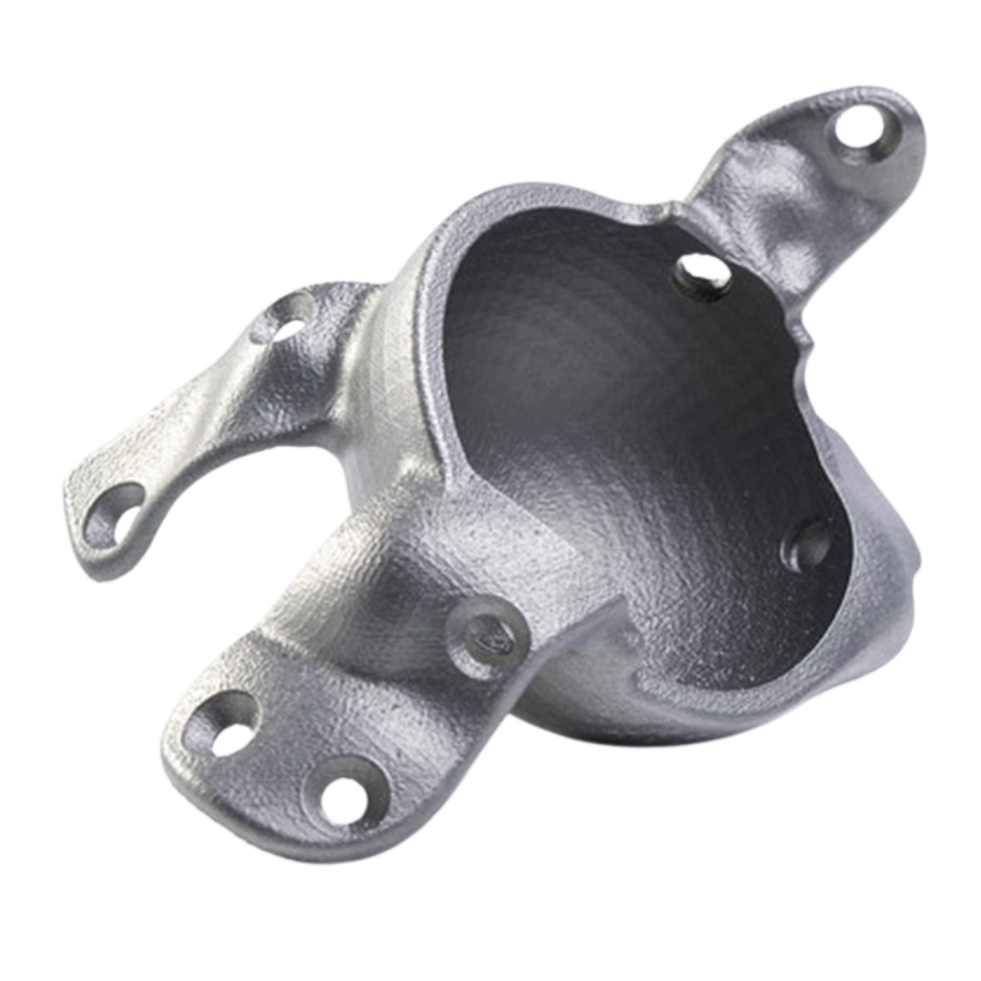
The precision of a hole depends not only on its diameter, but also on the thickness of the wall in which it is printed. The thicker the wall, the less accurate the hole can be. For holes that go all the way through, it must also be ensured that there is a clear line of sight so that all excess material can be removed during post-processing.
Minimal raised detail
A detail is a feature whose length is less than twice its width. The minimum size of details is determined by the printer resolution. If the detail dimensions are below this minimum, the printer may not be able to reproduce them accurately. Details that are too small can also be smoothed out during polishing and thus disappear.
To ensure that details are clearly displayed, they should be larger than the specified minimum. We may not be able to print products with details below the minimum size as the end result will not match your design. If your product contains smaller details, try to enlarge them, remove them or choose a material with finer detail reproduction.Minimal engraved detail
A detail is a feature whose length is less than twice its width. Engraved or recessed details are those that go into a surface.
Minimum distance between components
The distance is the space between two parts, walls or wires. To achieve a successful print result, the gap between parts, walls and wires should be greater than the specified minimum. If the distance is too small, it may help to increase the gap or connect the parts or features if their independence is not necessary. Alternatively, a material with a smaller minimum gap can be selected.
Included parts possible?
Sometimes interlocking or moving parts cannot be printed because the supports inside the cross-section cannot be removed.
Support structures needed?
As each layer must build on the previous one, some materials at angles greater than 45 degrees usually require supports to be printed along with the design. Supports are not inherently detrimental to your design, but they increase the complexity of the printing process and result in a less smooth surface on overhanging parts.

Weather resistant

Heat resistant

Elastic

High strength

Chemically resistant
